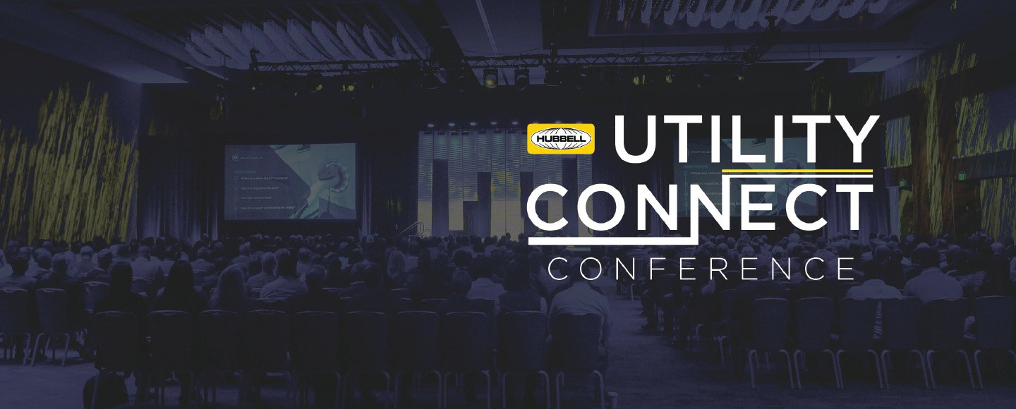
For sales and support visit:
hubbellpowersystems.com/contact/

Welding Aluminum Buses and Connectors

Recommended welding procedures to ensure a sound weld are as follows:

Pure aluminum melts at 1220° F while aluminum alloys melt in the range of 1020° F depending on the alloy content of the particular metal involved. When aluminum alloys are heated there is no color change. This makes it difficult, if not impossible, to tell if the metal is near the welding temperature. The ever present surface oxide films on aluminum have a melting point of 3600° F. The parent aluminum or aluminum alloy can therefore be melted without fusing the surface oxides. Unless the film is removed, cleanliness of the molten filler metal and the parent metal cannot be complete and both strength and conductivity may be sacrificed. Therefore, it is of prime importance that the aluminum oxides be removed from the aluminum alloys before welding is started. In the shielded arc welding method the shielding gas has a tendency to clean the material as welding progresses.


Cleaning of Buses and Fittings


It is very important to remove all greases and oxides from the surfaces to be welded. This can be accomplished by using a mild alkaline solution or standard degreasing solution. The preferred method is to use a stainless steel wire brush and vigorously scrub the surfaces to be welded. The stainless steel brushes are specified because the stainless steel has less of a tendency to pick up particles of aluminum and aluminum oxides.

Welding Methods


Anderson recommends the following two types of welding methods for welding aluminum fittings and buses:

  1. Tungsten-Arc Welding (TIG)


    The inert gas shielded tungsten-arc process is widely used for welding aluminum bus fittings. In this process the arc is established between a non-consumable tungsten electrode and the section to be welded. Inert gas envelops the arc to prevent oxidation during welding. Hence, no flux is required. A bare filler rod supplies filler metal to the weld area. To initiate the arc the tungsten electrode is placed in contact with the component and then withdrawn to establish an arc length of approximately 3/16". The arc is given a circular motion until the base metal liquifies and the weld puddle is established. Filler metal is added by hand as required. In this process, if more than one pass is required for a sufficient weld, the weld should be wire brushed between passes to remove any surface dirt or oxides which have accumulated from the previous pass. Since no flux is used the finished weld does not require cleaning. In this process the heat of the tungsten arc is concentrated in a smaller area and is much faster than the conventional type of welding and distortion of the weld is negligible since the heat is concentrated in a small area. In this process, if thicknesses greater than 1/ 2" are to be welded, preheating of the parts before welding will increase the welding speed.
  2. Metallic-Arc Inert-Gas Shielded Welding


    The consumable electrode inert-gas shielded metal arc (MIG) welding process combines the advantages of tungsten-arc welding with increased welding speed. Welding can be done from any position and the process can be either manual or automatic. Manual welding techniques are somewhat different from other methods. However, a welder can be trained to use the MIG process with only a few days concentrated training. In the MIG process the bare filler rod is supplied as a coil of bare wire. In the commercially available equipment this wire is added to the weld at a predetermined rate by a motor-driven feed that can be adjusted to the magnitude of the welding current. In this process, as well as the tungsten-arc process, gas forms a shield around the arch to prevent oxidation during welding. Either helium, argon or a mixture of helium and argon are suitable shielding gases. Pure argon is most widely used on sections less than 3/4" thick. On sections over 3/4" thick the gases are usually mixed to combine the hotter arc characteristics of helium with the stabilizing effect of argon. If exceptionally hot arc characteristics are required, pure helium can be substituted for the gas mixture. Precaution should be exercised if this substitution is made in that it is very easy to burn through the items that are to be welded with a pure helium atmosphere.

The reasons that Anderson has selected the metallic-arc inert- gas shielded welding method is that in this process the filler metal can be automatically fed through the welding mechanism and eliminates holding the electrode holder in one hand and the filler metal in the other as in the tungsten arc method. Figure 1 of the attached drawing shows the basic components for a metallic-arc inert-gas shielding process (MIG) and Figure 2 shows the basic components for the tungsten-arc process (TIG). As it is readily apparent, the basic difference between the two types of welding apparatus is the automatic feeding mechanism for the filler wire.

In both types of apparatuses the electrode holder and the welding gun can or cannot be cooled by water. If welding currents of more than 125 amps are required, both methods will have to have water cooling aparatuses to the electrode holder and the welding gun.

Welder's Qualifications


In both types of apparatuses the electrode holder and the welding gun can or cannot be cooled by water. If welding currents of more than 125 amps are required, both methods will have to have water cooling aparatuses to the electrode holder and the welding gun.

The following is Anderson's recommended specification for current fittings, wire feeds, gas flows, etc. These specifications are of a general nature to the extent that many factors have to be considered such as:

  1. Type of equipment used, whether water cooled or not, etc...
  2. The size and mass of the piece to be welded.
  3. The position of the weld.
  4. And most important of all, the operator's skill.
  5. All persons in the welding area should wear the appropriate shields. The arc is approximately twice as strong as the standard AC welding arc. Extreme caution should be exercised for the protection of eyes.
Metallic-arch inert-gas shielded welding (MIG) Inert-gas shielded tungsten-arch welding (TIG) Fig. 1 Metallic-arch inert-gas shielded welding (MIG)                       Fig. 2 Inert-gas shielded tungsten-arch welding (TIG)
Hubbell Power Systems All contents Copyright© 2001 - Hubbell Incorporated. All rights reserved. Because Hubbell has a policy of continuous product improvement, we reserve the right to change design specifications without notice.
Terms of Use | Contact Us | Site Map
Connectors